comment 0

Physical Computing: Final Project Log

For my final project I wanted to move away from the world of Arduino and explore building synthesisers using integrated circuits. I’d had quite a bit of experience with microcontrollers before this course, so decided to challenge myself with something more foreign to me: stepping back from the code and focusing on the electronics (definitely where I struggle the most).

01

03

02

If you don’t feel like reading, here is a video detailing some of the work I completed over the last few weeks, testing out different circuits and components:

Step 1: Initial concept (23.02.16)

My initial idea is to build a noisy drone synthesiser, focusing on microtonal adjustments as opposed to the western 12-tone scale. In particular I’m taking inspiration from Casper Electronics’ Drone Lab and Nova Drone. Here are some videos of the instruments in action:

I want the synth to have three “banks”, each with its own set of controls. The banks would be divided into low, middle, and high frequencies. Each bank would have two oscillators, potentially made from a 556 timer chip, and could have the following controls:

  • Volume
  • General Pitch
  • Fine-tune pitch
  • Detuning oscillators
  • Based on the amount of time I have, each bank may also have a controllable low frequency oscillator which would affect the volume. In this case, the volume control would determine the upper volume limit.

Currently I plan to use potentiometers to control these parameters in order to make microtonal/gradual adjustments. However, I am open to employing more uncommon components if they will enable to me explore different methods of control without feeling too gimmicky. In this project I am placing more importance on function over novelty, as it is something I would like to use in future performances. If I include LFOs on each bank, they could also have an on/off toggle.

I would also like to explore simple analog video synthesis, if time permits. I would aim for something dreamlike, or attempting to convey the visual equivalent of drones – whatever that might be.

In a perfect world, my inputs would therefore be:

  • Three banks of potentiometers
  • On/off toggle
  • A toggle switch for each bank
  • Potentially alternate components for parameter control (pressure, capacitive touch etc)

And my outputs would be:

  • Mono audio
  • Composite or VGA video

The enclosure must be robust and portable enough for me to take the instrument around to different performance venues. Therefore I will probably use aluminium enclosures, like those used for guitar effects pedals. I would prefer it to have a compact form factor so as not to be obtrusive or take up too much space on whatever surface I am using it on, whether that be during a performance or home recording.

Step 2: Designing schematic

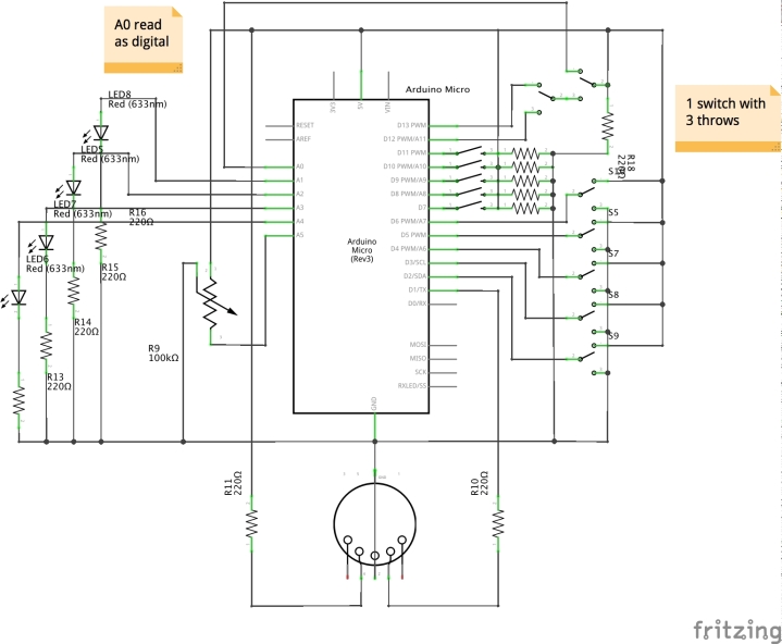
I decided to draw a kind of “pseudo-schematic”, equivalent to pseudo-code that programmers write to describe a program or algorithm at a higher, more comprehensible level. I’ve focused on how I would control three banks, with two oscillators each, both being controlled by the same potentiometers.

PseudoSchem

In this sketch, each oscillator pair has a volume and pitch potentiometer. Then, one oscillator in each pair is  connected to another potentiometer in to further change its pitch, resulting in detune functionality.

Step 3: Sourcing components

After much deliberation, I  have ordered a range of potentiometers to test out: a range of stereo potentiometers, both linear and logarithmic, of various resistances, and some 10k and 1k linear potentiometers. I intend to use the 1k pots as the detune, as they should give me finer control.

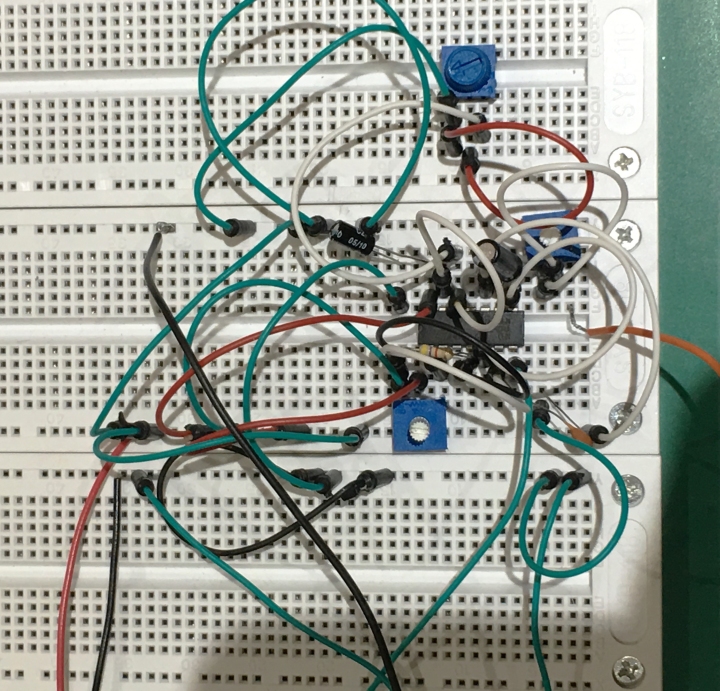
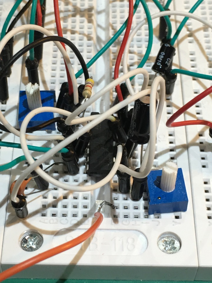
Step 4: Breadboard prototyping (07-19.03.16)

Over the last few weeks I have been testing different components and circuits. I have found that the potentiometers did not behave as expected, in several instances. For example, the 1k potentiometers did not give me the finer control I was looking for – instead they gave me only a very slightly smaller pitch range.

However I did find some interesting effects with the stereo potentiometers. Though they also did not behave as I had expected, I did manage to achieve a crossfading effect between oscillators, which could be an interesting route to follow in the future.

Furthermore, I experimented with diodes to create a ring modulation effect. Though this wasn’t the sound I was looking for, it was a lot of fun! During this point of the project I also experimented with light dependent resistors to control the pitch. It was also a fun to play with, but rather gimmicky and hard to control – not great for real-world use.

The main issue I found here, along with the potentiometers, was the different pitches of the oscillators. I tested a few chips, and on one side the pins resulted in an oscillator of a much higher (and annoying) pitch.

At this I decided to refine the idea down to its core – the emerging complexity from the  interaction of two simple oscillators.

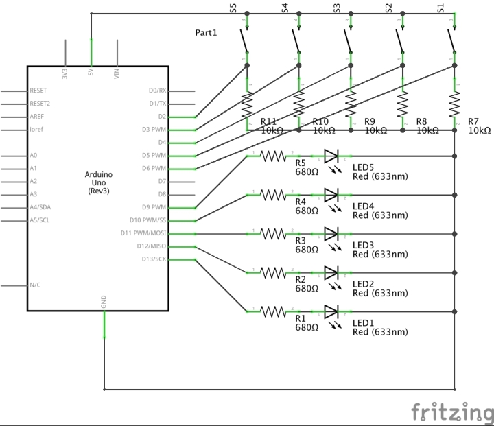
Step 5: Refining schematic (19.03.16)

FinalPhys_Toggle_schem

This is the updated schematic of my project, showing the simplified circuit that emphasises the interaction I’m looking for. I want to make this an ultra-portable pocket synth that can be used as sound source in performances and recordings. It could also be a prototype for a very simple oscillator Eurorack module.

Step 6: Building

I chose to use 10k potentiometers coupled with 22uF capacitors, since they gave me the widest useable control from rhythmic pulses to pure tones. To go with my idea of a small form factor, I used an Altoids mint tin as the enclosure – joining a long-running community of Altoid tin projects. The main challenge I found was fitting everything inside of the tin; I could have easily switched to a bigger enclosure, which would have given me much more room to play about, but I wanted to stick to ultra-portability.  Because of the shallowness of the tin, I had to switch to using a mini-jack input, but eventually, I managed to get everything in with room to spare!

Step 7: Reflection + Future Development

In reflection I am pleased with the final outcome, as I have achieved my goal of creating an interesting sound source that uses interacting waveforms to generate complexity, in a very small form factor. It is definitely something that I could go out and use tomorrow as part of a performance.

However, I  believe there is definite room for more functionality. First, I would implement the power toggle I had tested, as well as an indicator LED. Then, I would like to build out the full drone machine detailed above – basically three of these pocket synths combined together, with some different potentiometers.

I would also like to experiment with different chips, like the CMOS 4070 that creates more non-harmonic sounds, which could be interesting to play about with.

Thanks for reading!

comment 0

Physical Computing [Lab 04.b]: Atari Punk Console

At the end of my blog post on Lab 04, I mentioned a tutorial video from Collin’s Lab, on how to build the Atari Punk Console. Since then, I’ve given it a shot (with mixed results). With some help from Phoenix Perry, we got it working. It’s a bit of a jungle of cables, but it works!

01.jpg

IMG_0798.jpg


comment 0

Physical Computing: Midterm Project Log

Over the last few weeks I’ve been working on my midterm project – a MIDI sequencer using the bell ringing concept I’ve talked about previously on this blog. It didn’t end up being massively successful, but I made a lot of personal progress. Check it out:

Step 1: Sourcing components

For the first few weeks of this project, I was torn between two ideas: the Forrest Mims Toy Organ that I mentioned in the blog post on Lab 04, and what I ended up choosing – the Quasimodo Bell Sequencer. I wanted to complete both projects, so took some time sourcing all of the components from electronics shops and online.

Step 2: Designing schematic (15.02.16)

I decided to sketch out the schematic of the Quasimodo project in order to confirm that I had the components needed, and to confirm the flow of the circuit.

Quasimodo_schem

I wanted to include –

Inputs:

  • 5 switches to turn on and off each ‘bell’
  • 5 buttons to allow for MIDI learn capability
  • MIDI Input
  • Potentiometer for tempo
  • Potentiometer for bell duration
  • 3-way switch for changing between 3-, 4-, and 5-bell patterns

Outputs:

  • 5 LEDs, one for each ‘bell’
  • MIDI output

…but I ran out of pins on the Arduino to add all of the features I wanted, and consequently simplified my design.

Step 3: Breadboard Prototyping (18.02.16)

I began prototyping the different segments of my project – LEDs, switches, MIDI output – using a breadboard. This helped me to determine whether I could get all of my components to function properly, before they were assembled and soldered together. This was important, because it allowed me flexibility to experiment and redesign my project. During this stage of the process I was able to achieve MIDI and LED output.

Step 4: Refining schematic (21.02.16)

Here is the simplified schematic that I will be building:

Quasimodo2_schem

Step 5: Building on perf board (22.02.16)

Building the project using perf board was something I had a continual struggle with. I began with the different components working on the breadboard, then transferred them over to perf board and soldered them down. During this stage of the process I had to be relocated several times, interrupting my ability to solder and limiting my access to tools. Consequently I couldn’t drill holes into my enclosure when I had planned to, and focused on soldering instead. This meant that I soldered down lots of my components on the perf board…outside of the enclosure. And consequently I will have to redo most of today’s work, tomorrow.

I also came across a problem with the toggle switches I was using, in that I would switch them on and the LED would flicker on and off. I’m not sure whether this is to do with my connections or something else.

Step 6: Rebuilding it right(ish) (23.02.16)

Today I completed most of the (re)construction of my project, soldering all of the LEDs, switches, and MIDI connector. To test that things worked, I coded the switches to turn the LEDs on and off – not the final result that I want, but it signified whether things worked or not. I managed to fix yesterday’s issue with the toggle switches by using some debouncing code from the Arduino examples. I had success soldering all of the components together, and used a lot of electrical tape around the connections to try and eliminate any crossed wires. It worked! However, when I started to cram everything inside of the enclosure, things started to go wrong and the LEDs started flickering. I’m not sure if this is because of loose connections or problems with the perf board, but much of it is under layers of electrical tape I have run out of time to fix it.

Step 7: Reflection

I didn’t manage to complete my project, and create the functional synthesiser that I wanted to. Therefore I think it is important to reflect on the process, and understand where I could have done better. Here are some of the reasons I can see as to why I didn’t achieve what I’d hoped:

  • Indecision: I took too long deliberating what project to focus on, and spent a lot of my time working on extension projects for my lab tasks (which also didn’t turn out…) instead of this major project. This was part of the reason I ran out of time.
  • Logistical: Unfortunately, several days that I had scheduled to work on my project were interrupted because of logistical reasons – the lab became out of action (albeit for massive improvements) for several days, and I was thrown out of work spaces twice. Whilst this is not an excuse to fail, it did throw me and inhibit my ability to work when I had planned to.
  • Complexity: I tried to cram too many components and functionality into the project, given the time I had to complete it. I had never worked with MIDI input or output before, and whilst I did get output to work rather easily, the input would have been more complicated. I had also never used this particular kind of toggle switch before, and had to understand how they worked, including debouncing.
comment 0

<3

LED_heart

Does anyone here love electronics?

I put this together as a Valentine’s Day gift for my girlfriend, but couldn’t show it before then for obvious reasons. Thankfully, she was thrilled.

comment 1

Physical Computing [Lab 04]: Making Noise

This post combines some experiments I did over a few weeks, using a couple of different integrated circuit (IC) chips – the 555 timer and the CD40106.

555 Timer

01/02/16: I started playing around with the 555 chip after getting Forrest Mims’ Timer, Op Amp & Optoelectronic Circuits and Projects book, as I wanted to try making some small synths. Both the 555 and the CD40106 are good for creating simple oscillators, the pitch of which can be controlled using resistors and capacitors. In the video below, you can see how even touching these components can cause deviations in pitch.


18/02/16: After spending the past week gathering components and an enclosure, I started building the Toy Organ project from the aforementioned Mims book, which I decided would be my submission for Lab 04. The project is a simple synth that buzzes at different pitches when you press different buttons down. However, I had mixed success. On the breadboard, I was able to make the system work – I tried a few different capacitors, and they generated different tones. I tried implementing button control, although the effect was reversed: when I pressed the button down, the tone stopped. However, this was fixed when using a different type of button I had bought for the final result. When it came to soldering the circuit onto perf board, I had no luck. I tried it twice, with two different chips, on two different boards – but nothing. I think I need another pair of eyes to help me spot what’s going wrong.


Here are some examples I found of similar projects that can be achieved using the same 555 chip:

I also came across an interesting teardown of the 555, showing what exactly is in the chip and how it works in great detail. Check it out if you want more info!

CD40106

The CD40106 is another great chip that is used a lot in Nicolas Collins’ seminal Handmade Electronic Music. Here is a great tutorial by Casper Electronics on how to make a simple synth using the CD40106, closely following Nicolas Collins’ book:

10/02/06: I started following the tutorial and playing around with a light dependent resistor to create a very simple controllable oscillator. Changing out the capacitor gives a different tone, so I bought a whole box of them to try! I definitely prefer the lower pitched ones…

Bonus!: 556

I also came across an Instructable that shows you how to make an Atari Punk Console using a 556 chip (a 556 = two 555s). Definitely want to give this a shot!

comment 0

Physical Computing [Lab 03.b]: Human Detector

[Dear Phoenix & Perla: My full lab write-up, including the rest of the tasks, was submitted online through learn.gold]

In my last Physical Computing update, I hinted at my lab project: The Human Detector. But what is a human detector? How does it function? Does it work? All valid questions – so let’s get to it.

REQUIREMENTS: What design problem are you going to solve with this task?

This system must detect the presence of a human.

It does this by presenting any humans in the immediate area with a big red button, exploiting humans’ inability to resist pressing big red buttons.

ANALYSIS: What hardware components will you need? What software will you use to support the requirements?

The required hardware components are: Arduino Uno; 9v battery; 680Ω resistor, 10kΩ resistor; light dependent resistor; momentary push switch (the aforementioned ‘big red button’); piezo buzzer; red LED; servo; red cardboard arrow; perf board; wire; plastic enclosure; black electrical tape.

The Arduino Uno will be coded using the Arduino IDE software.

INTERACTION DESIGN: What kind of interaction will the system support. What are the inputs and outputs?

The Human Detector supports two layers of interaction. The primary layer of interaction centres around the big red button. When pushed the circuit becomes complete, turning the LED and piezo buzzer on and signalling for the servo to point towards the button — and by extension, the human.

The secondary layer of interaction is provided by the light dependent resistor, located just under the button. As the human reaches towards the button, they will change the amount of light hitting the resistor. This fluctuation is used to animate the servo back and forth as if it has begun to detect a human, and is searching for their position.

NOTES AND TESTING: What problems did you encounter and overcome? 

Most of the problems I had were encountered during the construction phase, when moving from a breadboard prototype to a more permanent solution. Making the enclosure required drilling holes into the plastic box; this was very imprecise, due to the nature of the material and my inability to properly handle a drill. Consequently the holes on which to mount the components are very rough, irregular, and unattractive. To combat this, I used electrical tape to cover the holes.

This was also one of the first times I used perf board. I struggled with getting the solder to stick to this particular board, and so my connections quickly became messy and hard to control. Some cold solder joints had to be redone. Since I wasn’t working on a breadboard, I also had to solder my own power and ground rails. At one point, I even ran out of space on the particular row I was working on, so had to connect multiple rows by making a jumper wire.

After soldering components down, I would cut the legs off. But problematically, I had to re-solder some parts due to certain errors. This meant that I had trouble when joining the components back, as the legs were now too small. Consequently, I had to buy another light dependent resistor in able to complete the project.

Furthermore, I had to slightly redesign my circuit, as the prototype used a push-button switch with four legs — two on each side — which came with my Arduino kit. However, the momentary push switch (big red button) that I bought only has two legs. Consequently, I had to move the resistor in order to fit it into the circuit.

Finally, the end result is not foolproof. Some humans are able to resist the lure of the big red button and will escape detection. Other more reliable methods of capturing human attention are currently under development.

DIAGRAMS:

Human Detector_bbHuman Detector_schematic

CODE:

Available on my GitHub.

So does it work?

Well…not really.

As you can see from the video above, when the button is pressed the LED on the Arduino blinks. However, the red LED that I’m using does not, and instead seems to float between on and off. Perhaps I am missing a pull-down resistor somewhere…

If I can find the time, I’ll return back to this project to try and fix it. But for now, I’m going to focus my attention on the final lab and first major project.


comment 0

Lumiere London: FIELD’s Spectra-3

The Lumiere light festival hit London this January, showcasing a whole host of installations across London ranging from flying fish to projections mapped on some of London’s most loved buildings. I was lucky enough to help out with FIELD’s installation, titled Spectra-3.

The third in the Spectra series of installations, it is described as: “an immersive audio-visual light experience: A physical-digital sculpture that tells three stories of communication, through a choreography of movement, animated lights and spatialised sound.”

Processed with VSCOcam with s2 preset

The result was hypnotising and beautiful to watch. The space was also filled with a score coming from a multi-channel setup that encompassed the sculpture, creating an absorbing atmosphere.

As well as helping FIELD install the sculpture I worked on the documentation shoot, assisting the lovely James Medcraft to photograph and film the installation. It was very chilly but we powered on through the night and early hours of the morning, and had a truly enjoyable time.

IMG_0225

Executive producer and FIELD co-founder Vera-Maria Glahn

Thank you to all of the team for including me on a great installation, and congratulations on the final result – here’s to Spectra-4!

More information about Spectra-3 can be found on FIELD’s website.


comment 0

Physical Computing [Lab 03.a]: Servos and LEDs and Motors, Oh My!

This week we started experimenting with a bunch of different components, from DC motors…

Week 3 Servo

…to servos…

Week 3 Servo

…and light dependent resistors!

Week 3 LDR

The above motor and servo experiments were created using code from the Arduino examples, and the automatic night light was built from this article.

After getting these components to work, we had a couple of tasks to complete. First of all, was to solder three LEDs and resistors to some perf board, then make them blink randomly. I busted the leftmost LED at some point, but can demonstrate that the circuit works by holding a fresh one to the back of the perf board.

Week 3 LED Random Flash

To make the LEDs blink randomly, I decided to use a random number generator. A random number between 0 and 299 was rolled; if it was between 0-99, the LED on pin 13 would flash; between 100-199 and pin 12 would flash; etc. Here it is in the code:

int rand = random(0,299);
int pin;
 
 if (rand >= 0 && rand <= 99){
   pin = 13;
 }

 else if (rand >= 100 && rand <= 199){
   pin = 12;
 }

 else if (rand >= 200 && rand <= 299){
   pin = 4; 
 }

digitalWrite(pin, HIGH);
delay(200); 
digitalWrite(pin, LOW); 
delay(200);

I’m not certain that this is the most elegant way of solving this problem (in fact I’m sure it’s not), but it works. And at this point, that’s all we can really hope for.

The final task for this week was to create a circuit by which a servo and LED could be controlled with one component. I chose to use the potentiometer, as I liked the direct relationship between the position of the servo and the pot; it seemed less gimmicky and more practical.

Week 3 Servo LED

Playing with this new toy, it suddenly struck me. As I turned the potentiometer, the servo began to point at me, and the LED lit up, almost like some kind of….human detector? So I decided to throw practicality to the wind and fully embrace gimmickry, and start building a fully-fledged human detector as my lab submission. See the results next time…

And, as always, you can see the code for this week on my GitHub.

comment 0

Physical Computing [Lab 02]: Noisy Video Synth

Welcome back for week 2! Let’s see how our little LED friend is getting on…

Week 2 LED Pot small

Hooked up to a potentiometer? Nice! That serial data looks great.

But could we perhaps use it for something a little more interesting? Something like…a noisy visual synth??


Of course we could!

So what’s going on here exactly? Well, we have a potentiometer hooked up to an Arduino Uno, which is sending values from 0-1023. This data is then sent to two places.

Firstly, the data is read by the Arduino and controls the tone coming from the surface transducer (basically a speaker without a cone – put it on something to hear it resonate!). I’m using the standard firmata example to grab the data and send it to openFrameworks, with some musical additions at the very bottom. I’ll paste them here for convenience:

 // MUSICAL ADDITIONS---------------------------------------------------------------

  int potValue = analogRead(A0);
  potValue = map(potValue, 0, 1023, 55, 110);
  int pause = 2 * 1.30;
  tone(8, potValue, 500);
  delay(pause);
  noTone(8);

So we’re reading the value from the potentiometer (on the analog pin 0) and mapping it to a range of 55-110Hz. This way you can get some nice clicking and buzzing, and even some phasing with the weird constant buzz that could either be coming from the surface transducer or the code. Who knows.

The data is sent to an openFrameworks project I adapted from a textbook, and have been using for live visual performances. I wanted to utilise what Hunt and Wanderly refer to as “one-to-many” mapping, with one component influencing multiple parameters. Using some code from the standard firmata example in openFrameworks, I was able to take the data from the pot and mapped it to eRad (the radius that the particles are constrained within), bornRate (how often new particles are created) and rotate (the direction and speed of rotation). Here’s the relevant code:

//--------------------------------------------------------------
void ofApp::analogPinChanged(const int & pinNum) {

    // analog pin event handler, called whenever an analog pin value has changed
    
    // do something with the analog input. here we're simply going to print the pin 
    // number and value to the screen each time it changes
    
    potValue = ard.getAnalog(pinNum);
    
    param.eRad = ofMap(potValue, 0, 1024, 0, 650);
    
    bornRate = ofMap(potValue, 0, 1024, 0, 3000);
    
    param.rotate = ofMap(potValue, 0., 1024, -300, 300);
    
    
    cout << "eRad: " << param.eRad << "   " << "bornRate: " << bornRate << "   " <<  
         "rotate: " << param.rotate << endl;
}

As always, the full code is available on my GitHub.

See you next week!